Parameters & Electrical
Configurable Parameters
The OSCP-MK2 IMU offers several real-time configurable parameters, which can also be saved in non-volatile memory to maintain them at each start-up. Refer to the Commands page for how to configure them.
| Parameter | Configuration | Comment |
|---|---|---|
| Output Data Rate | 0 Hz, 100 Hz, 500 Hz | Operating mode. |
| Gyroscope Dynamic Range | ±125, ±250, ±500, ±1000, ±2000, ±4000 °/sec | Selectable range, applies to the MEMS gyroscopes. On the MK2E2, the optical gyroscope's range is fixed and not user-configurable. |
| Accelerometer Dynamic Range | ± 2 g, ± 4 g, ± 8 g, ± 16 g | Selectable range. |
| Inclinometer Dynamic Range | ± 0.5 g, ± 1.0 g, ± 2.0 g, ± 3.0 g | Selectable range. |
| Enabled Frame Type | RAW, EULER, QUATERNION, ROTATION MATRIX, GNSS | Each type of frame can be enabled or disabled. Controller Overruns can occur. |
Electrical Interface
Precautions
- Do not power-up the device with reverse polarity.
- Do not exceed the input power-up voltage beyond + 34 VDC.
Connections
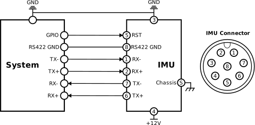
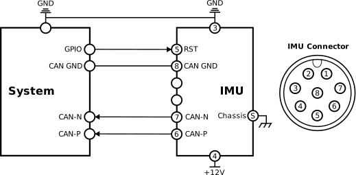
In order to operate correctly, the IMU must be connected as shown in the figure below, depending on selected protocol.
RST Pin
The active-high reset pin (number 5, wire color orange) can be left floating if unused.
The terminal provided to connect the IMU is open wired on the other side of the IMU connector. The table below shows wire identification. This pinout, connector, and wiring are identical across the whole MK2 family.
| Pin | Wire Color | Function Assignment | Comment |
|---|---|---|---|
| 1 | Red | RS422: RX- | Connected to user TX- (RS422) |
| 2 | Yellow | RS422: RX+ | Connected to user TX+ (RS422) |
| 3 | Black | Ground | Power Ground |
| 4 | White | Power | 12V Typical |
| 5 | Orange | Active-High Reset | Can be left floating. 3.3V, 5V Tolerant |
| 6 | Blue | RS422: TX+ / CAN-FD: P | Connected to user RX+ (RS422) |
| 7 | Green | RS422: TX- / CAN-FD: N | Connected to user RX- (RS422) |
| 8 | Purple | RS422 / CAN-FD: GND | Isolated Ground |
| Shell | Shield | - | - |
Otherwise, the IMU connector is 54-00251, its mating connector is 50-00983 and an example of mating cable assembly is 10-03817. All are from Tensility International Corp.