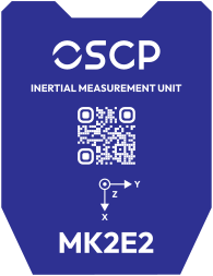
MK2E2
Revision
This documentation tracks REV10 (2026-08-21) and is preliminary — content is subject to change without notice. See the changelog for revision history.
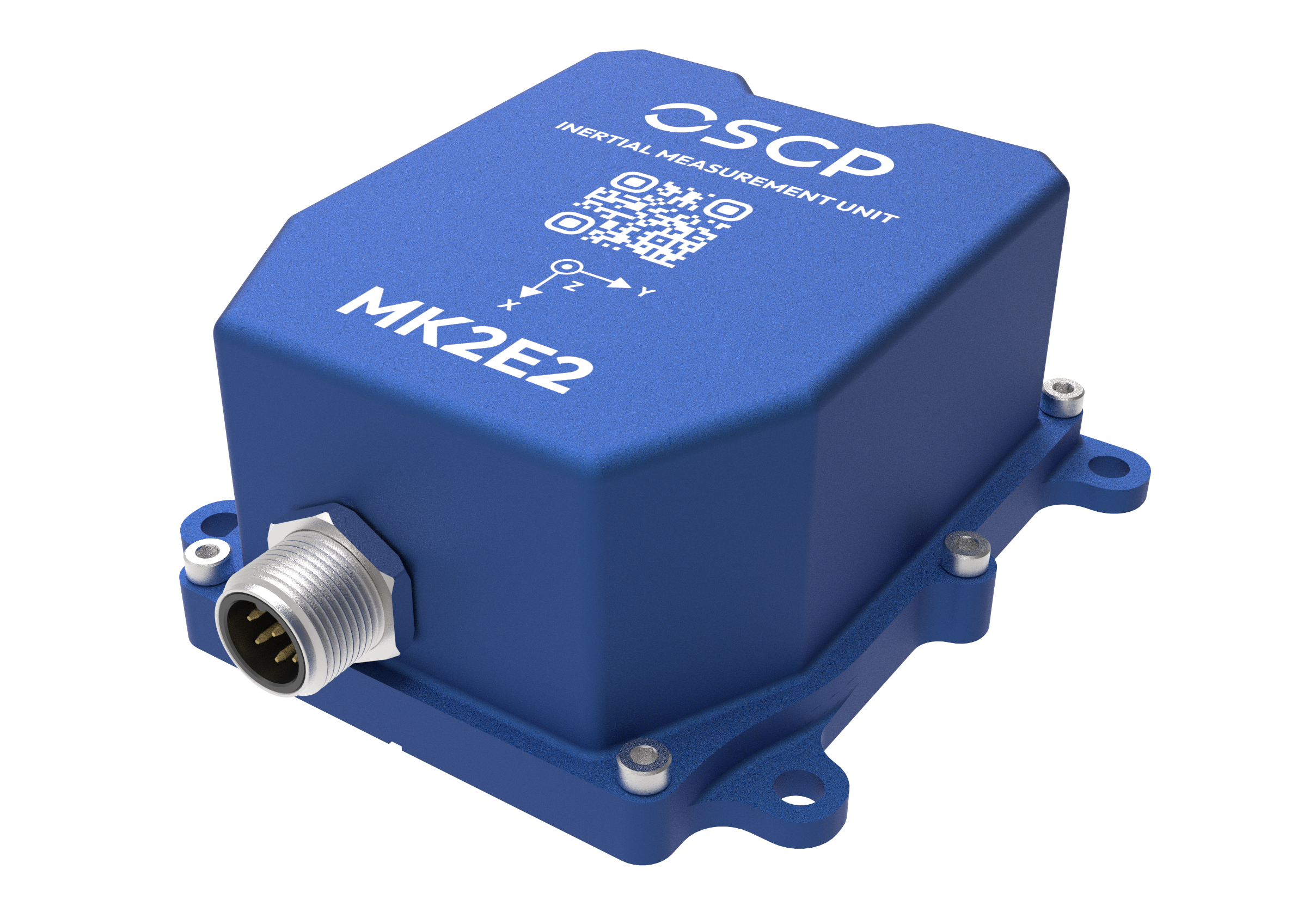
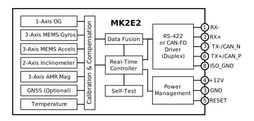
Our most versatile 11 degrees of freedom (DoF) unit — an IMU pairing a precision optical gyroscope on the heading axis with three MEMS gyroscope axes, three accelerometer axes, three TMR magnetometer axes and two inclinometer axes. The optical gyroscope enhances stability, making the MK2E2 exceptionally resilient to thermal drift, mechanical vibrations and EMI.
Applications
Autonomous heavy machinery · Precision agriculture · Construction · Aerospace · Defense · UAVs · Marine
Features
-
Precision optical gyroscope
On the heading axis (z) · 0.03 °/√hr ARW
-
Low-drift MEMS gyroscopes
0.5 °/hr in-run bias stability
-
Low-drift accelerometers
< 15 μg in-run bias stability
-
Interface
RS-422 or CAN-FD
-
Power
2 W · +12 to +34 VDC
-
Dimensions
78 × 63 × 36 mm1 · 230 g
-
Environment
−40 °C to +85 °C · IP57 · IP67 coming
Functional Block Diagram
Specifications
Indicative figures only
Values below are at typical operating conditions. Test conditions, min/max limits over temperature, scale factor and non-linearity errors are given in the full specification sheet — contact us at info@oscp.com to request it.
Optical Gyroscope (z-axis)
- Dynamic Range
- ±250 °/sec
- In-Run Bias Stability
- 0.5 to < 1.0 °/hr
- Angle Random Walk
- 0.03 °/√hr
Automatic z-axis source switching
The z-axis gyroscope output is sourced from the optical gyroscope while the measured rotation rate stays below 250 °/sec. Above that threshold the output switches automatically to the MEMS gyroscope, maintaining accuracy up to the selected dynamic range. No configuration or host-side handling is required.
MEMS Gyroscopes
- Dynamic Range (Selectable)
- ±125 to ±4000 °/sec
- In-Run Bias Stability
- 0.5 to < 1.0 °/hr
- Angle Random Walk
- 0.06 °/√hr
Accelerometers
- Dynamic Range (Selectable)
- ±2, ±4, ±8, ±16 g
- In-Run Bias Stability
- < 15 µg
- Velocity Random Walk
- 0.008 m/sec/√hr
Magnetometers & Inclinometers
- Magnetometer Dynamic Range
- ±20 G
- Inclinometer Dynamic Range (Selectable)
- ±0.5, ±1, ±2, ±3 g
Communications
- Protocol
- RS-422 or CAN-FD
- Output Data Rate
- up to 500 Hz
Electrical
- Operating Voltage
- 12 to 34 V
- Power Consumption
- 2 W
Mechanical
- Operating Temperature
- −40 to +85 °C
- Rating
- IP57 (IP67 in certification)
- Dimensions
- 78 × 63 × 36 mm1
- Weight
- 230 g
Important
All specifications are no longer guaranteed if the unit is opened.
Certifications & Environmental Testing
The MK2E2 has been validated by an independent ISO/IEC 17025 accredited laboratory.
Ingress Protection
- Rating
- IP57 — IEC 60529:2019 (IP67 in process)
Electromagnetic Compatibility
- Emissions
- EN 55032 Class A · FCC Part 15 · ICES-003
- Immunity
- EN 55035 / CISPR 35
Vibration & Shock
- Vibration
- Sine sweep 20–2000 Hz up to 8 g peak, all three axes
- Shock
- Half-sine up to 40 g peak, 11 ms, all three axes
About vibration and shock
Units were tested unpowered and verified functional afterwards. These figures describe what the unit survives, not its performance during exposure.
Mechanical Drawings
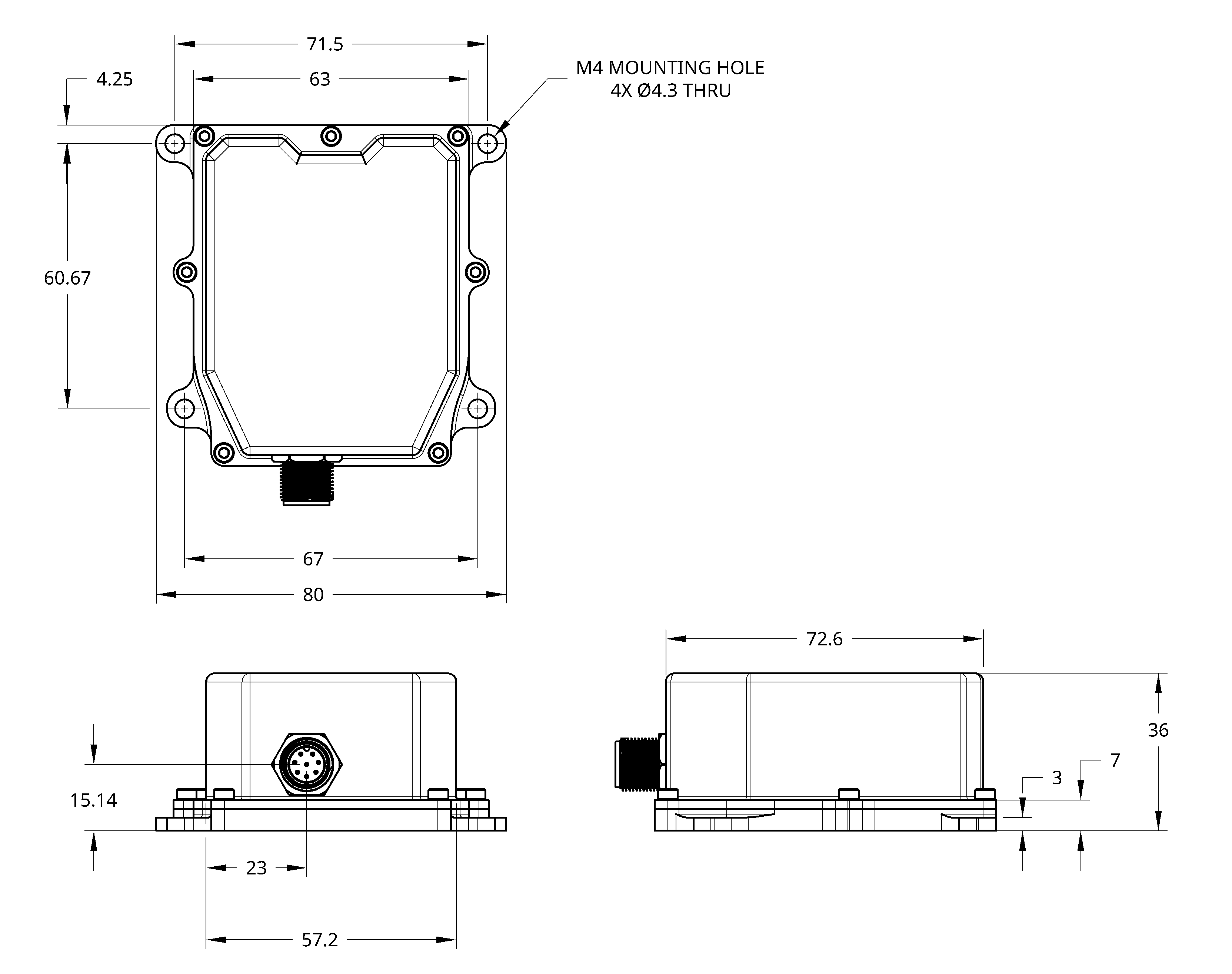
The enclosure features M4 mounting holes, with mechanical drawings showing the mounting through-holes and side views indicating the connector location. All units are given in mm.
Marking
The top of the package is marked with a decal indicating the orientation axes of the unit.